The Francis Turbine is a high-efficiency hydraulic turbine widely used in hydroelectric power plants. Operating on the reaction principle, it converts both pressure energy and kinetic energy of water into mechanical energy, which is then transformed into electrical energy via a generator.
This comprehensive guide covers the working principle, construction, velocity triangle, efficiency, advantages, disadvantages, and applications of the Francis Turbine—plus a brief comparison with the Kaplan Turbine.
⚙️ Working Principle of Francis Turbine
The Francis Turbine is a mixed-flow reaction turbine, meaning:
- Water enters radially and exits axially
- Both pressure and velocity energy contribute to rotation
🔄 Step-by-Step Operation:
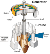
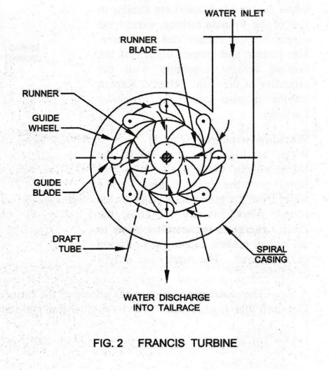
- Water Entry: High-pressure water enters the spiral casing from the penstock
- Flow Regulation: Guide vanes (wicket gates) control flow direction and volume
- Energy Transfer: Water strikes curved runner blades, transferring energy
- Runner Rotation: Water impact causes the runner and shaft to rotate
- Draft Tube Exit: Water exits axially, recovering pressure and reducing velocity loss
- Power Generation: The rotating shaft drives a generator, producing electricity
📐 Francis Turbine Power Formula
The power output is calculated using:
math
P = ρ × g × Q × H × η
Where:
- ρ = Water density (kg/m³)
- g = Gravity (9.81 m/s²)
- Q = Flow rate (m³/s)
- H = Net head (m)
- η = Turbine efficiency
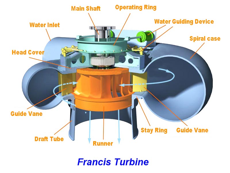
🛠️ Francis Turbine Construction & Diagram
Key components include:
- Spiral casing – Distributes water evenly
- Stay vanes – Provide structural support
- Guide vanes – Direct water flow
- Runner blades – Convert energy
- Draft tube – Facilitates smooth water exit
These parts work together to ensure optimal energy conversion and minimal hydraulic losses.
📊 Velocity Triangle in Francis Turbine
The velocity triangle illustrates the relationship between:
- Absolute velocity (V1, V2)
- Relative velocity (Vr1, Vr2)
- Tangential velocity (u1, u2)
- Whirl velocity (Vw1, Vw2)
- Flow velocity (Vf1, Vf2)
Key Angles:
- θ = Inlet vane angle
- Φ = Exit vane angle
- α = Guide vane angle
At the outlet, Vw2 = 0, indicating radial discharge.
📈 Important Ratios & Specific Speed
| Parameter | Formula | Typical Range |
| Flow Ratio (Kf) | Vf1 / √(2gH) | 0.15 – 0.30 |
| Speed Ratio (Ku) | u1 / √(2gH) | 0.6 – 0.9 |
| Width/Diameter (n) | B1 / D1 | 0.1 – 0.45 |
| Specific Speed (Ns) | Ns = N × √P / H^(5/4) | Application-based |
✅ Advantages of Francis Turbine
- High efficiency across a wide range of heads
- Compact and robust design
- Suitable for medium to high head applications
- Low maintenance and long operational life
❌ Disadvantages
- Not ideal for very low head conditions
- Complex design compared to impulse turbines
- Cavitation risk at low loads
🌍 Applications of Francis Turbine
- Hydroelectric power generation
- Pumped storage plants
- Medium-head water flow systems
- Renewable energy projects
🔄 Comparison: Francis Turbine vs Kaplan Turbine
| Feature | Francis Turbine | Kaplan Turbine |
| Flow Type | Mixed flow | Axial flow |
| Head Range | Medium to high (40–600m) | Low to medium (10–70m) |
| Blade Adjustment | Fixed or adjustable | Fully adjustable |
| Efficiency Range | High | Very high at low heads |